

DIY 150W Ultrasonic Cleaner Circuit Board Transducer Drive PCB Spare Parts for Ultrasonic Washing Bath and Tank Cleaning Systems
$1,400.00 piece
Upgrade your cleaning tank with this 150W ultrasonic cleaner circuit board. It delivers stable power output, simple installation, and reliable DIY performance.
Shipping & Delivery
-
 Express Air Delivery
Door-to-door with tracking
7-15 Business Days
Calculated at checkout
-
 Standard Ocean Freight
Best for bulk & heavy cargo
25-35 Business Days
Calculated at checkout
-
 Warranty 1 year
-
 Free 30-Day returns
Specification
 Overview
| Model | DG3-J150 |
|---|---|
| Brand | Granbo |
| Manufacturer | Granbo Technology Industrial Shenzhen Co., Ltd. |
| Origin | China |
| Frequency | 40kHz |
| Power | 150W |
| Voltage | 100V-120V ~ 60Hz / 220V-240V ~ 50Hz |
| Warranty | 1 Year |
| Applications | DIY Ultraonic Cleaner, DIY Ultraonic Machine, DIY Ultrasonic Cleaning Tank |
Packaging
| Chargeable Weight | 65.4 kg |
|---|---|
| Package Dimensions | 75 × 45 × 53 cm |
Description
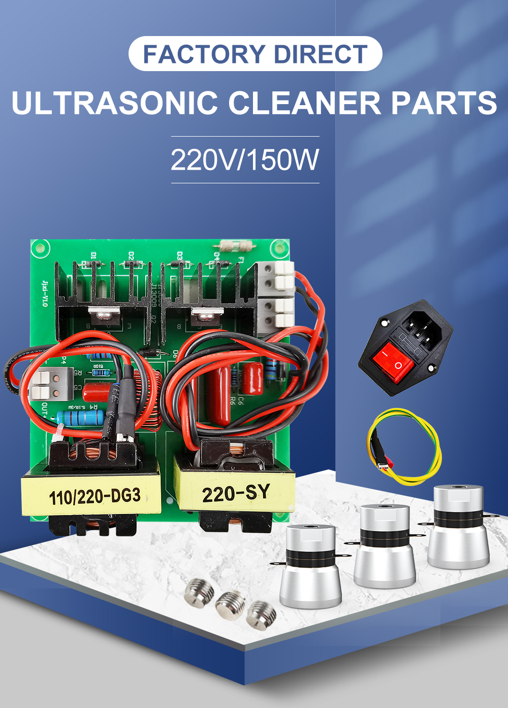
- Input Voltage: 100V-120V ~ 60Hz / 220V-240V ~ 50Hz (Shipped according to the destination country, or selectable by leaving an order note)
- High-Quality Components: Engineered for reliable performance.
- Simple Installation: Designed for direct wiring and assembly.
- Customizable Design: Adaptable to custom cleaning tank builds and configurations.
- Cleaning Output: Operates at 40 kHz for professional-grade cavitation cleaning.
- Cost-Effective Maintenance: Direct replacement kit without the need to replace the entire cleaning unit.
Drive Capacity
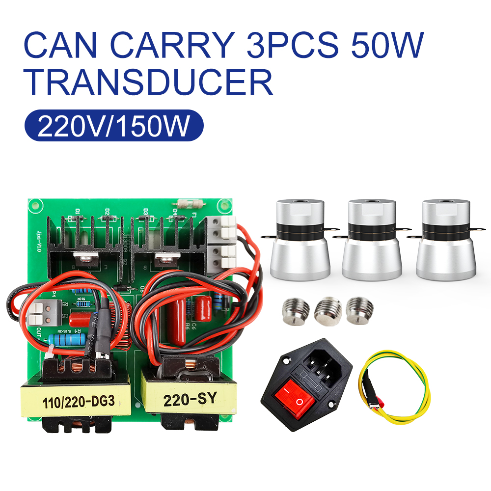
- Load Capacity: Drives up to 3 units of 50W ultrasonic transducers
- Total Acoustic Power: 150W
- Operating Frequency: 40 kHz
Package Contents
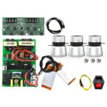
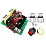
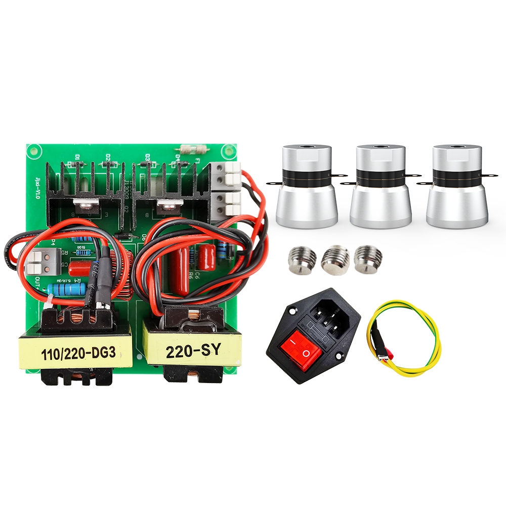
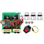
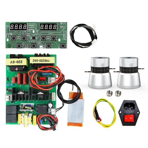
- 1 x 150W Ultrasonic Cleaner Driver Circuit Board
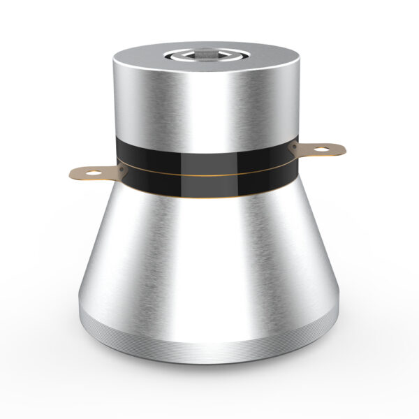
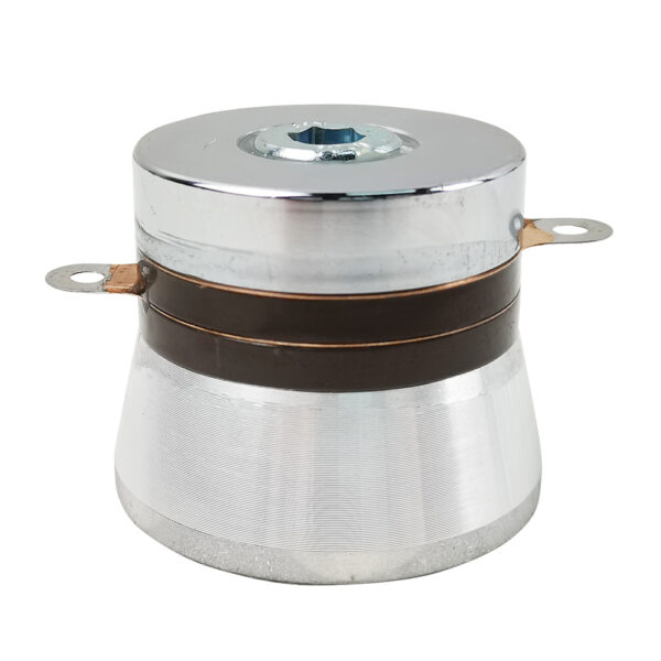
- 3 x 50W / 40 kHz Horn Type Ultrasonic Transducers
- 3 x Threaded Studs
- 1 x AC Power Socket with Integrated Switch and Fuse Holder
- 1 x Earth Wire
Technical Specifications
Circuit Board Specifications
- Rated Power: 150W
- Input Voltage: 100V-120V ~ 60Hz / 220V-240V ~ 50Hz (Shipped according to the destination country, or selectable by leaving an order note)
- Output Voltage: ~400V AC
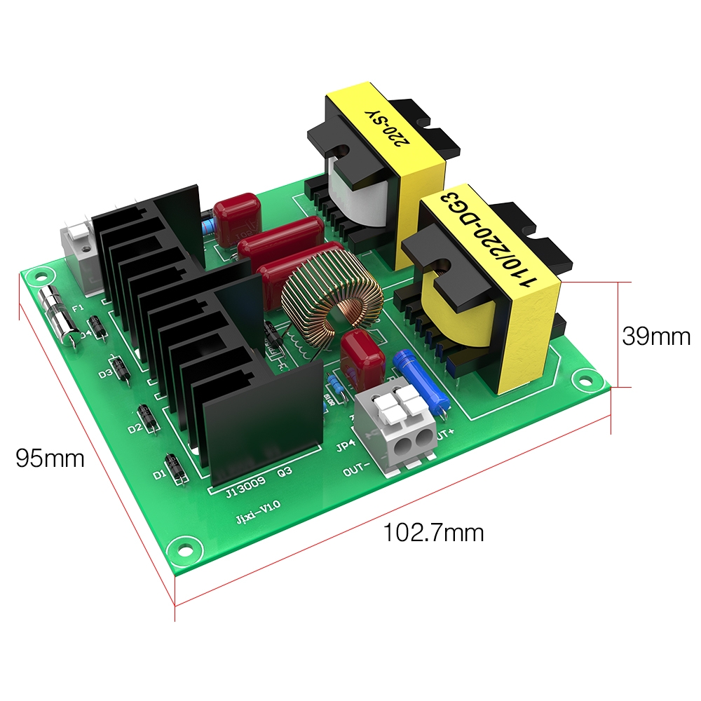
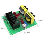
- Circuit Board Dimensions: 102.7 mm (L) x 95 mm (W) x 39 mm (H)
- PCB Model: Jixi-V1.0
- Output Interface: Spring-clamp terminals (OUT+ / OUT-)
Ultrasonic Transducer Specifications
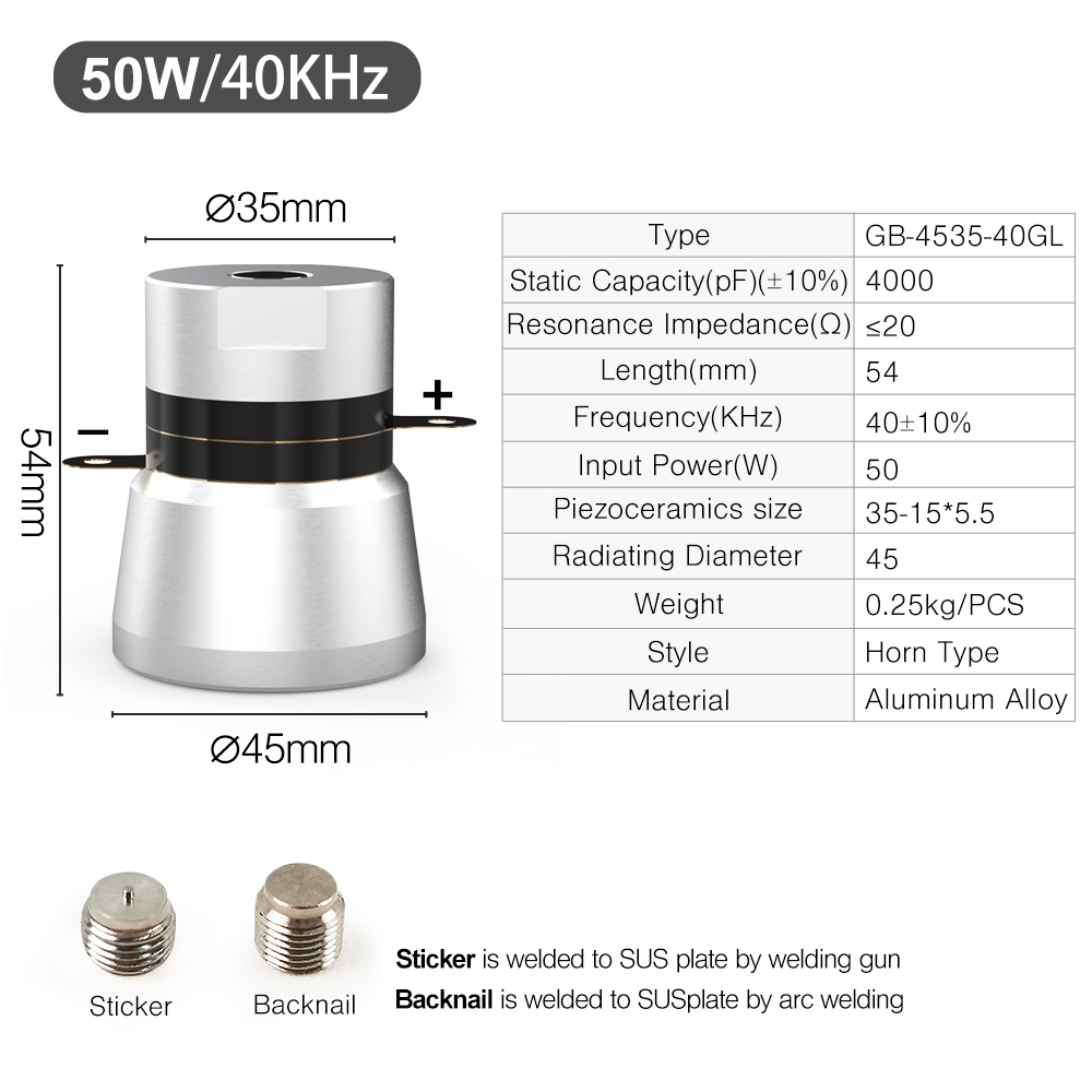
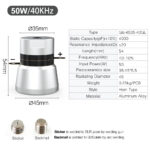
- Model: GB-4535-40GL
- Operating Frequency: 40 kHz ± 10%
- Input Power: 50W (per unit)
- Static Capacitance: 4000 pF ± 10%
- Resonant Impedance: ≤ 20 Ω
- Total Length: 54 mm
- Top Diameter: Ø 35 mm
- Radiating Surface Diameter: Ø 45 mm
- Piezoceramic Ring Dimensions: 35 mm (OD) x 15 mm (ID) x 5.5 mm (Thickness)
- Unit Weight: 0.25 kg / piece
- Transducer Style: Horn Type
- Housing Material: Aluminum Alloy
- Mounting Stud Options:
- Sticker (Point tip stud): Welded to the stainless steel plate with a stud welding gun.
- Backnail (Threaded stud): Welded to the stainless steel plate by arc welding.
Transducer System Wiring
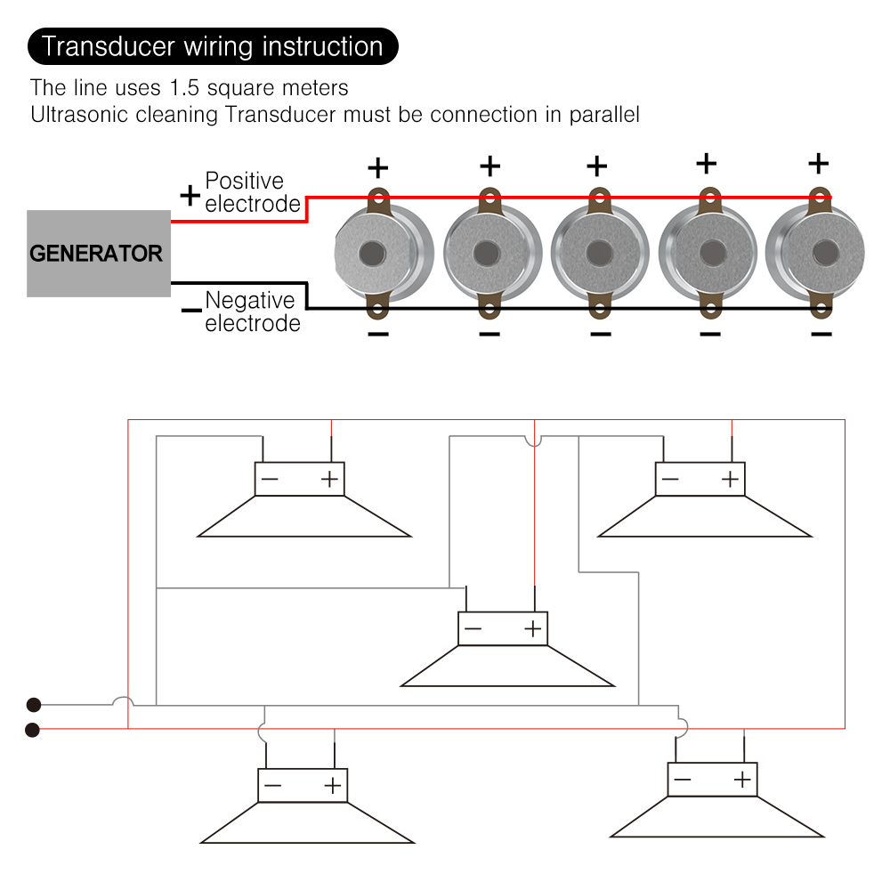
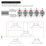
- Wiring Gauge: 1.5 mm² wire
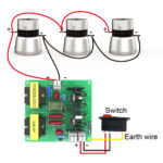
- Connection Mode: Ultrasonic transducers must be connected in parallel.
- Wiring Path:
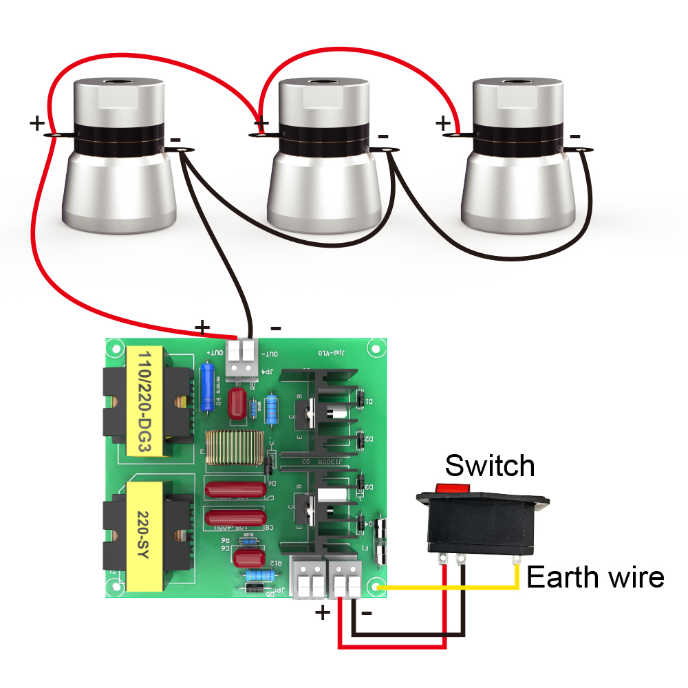
- Connect all positive (+) electrode lugs of the transducers to the OUT+ terminal on the circuit board.
- Connect all negative (-) electrode lugs of the transducers to the OUT- terminal on the circuit board.
- Connect the AC power supply switch to the board terminals (L and N).
- Fasten the yellow/green earth wire to the metal cleaning tank chassis.
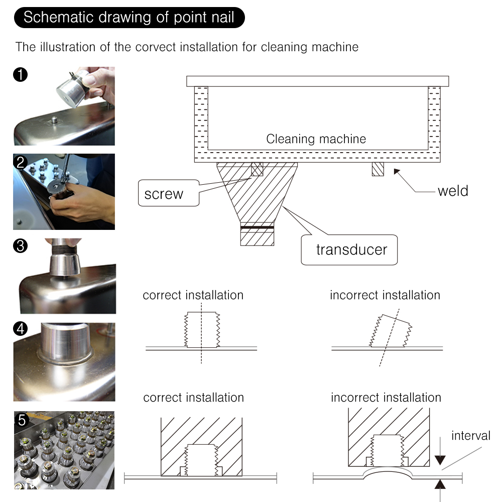
Transducer Installation Guidelines
- Perpendicular Stud Alignment: Weld the mounting stud strictly perpendicular to the tank plate. A tilted stud prevents full contact.
- Flat Surface Contact: The bottom radiating face of the transducer must sit flat against the stainless steel plate without gaps or surface deformations.
- Installation Steps:
- Step 1: Position and weld the stud onto the stainless steel plate.
- Step 2: Apply bonding epoxy/adhesive to the radiating surface.
- Step 3: Thread and screw the transducer onto the welded stud.
- Step 4: Ensure the interface between the transducer base and the tank plate is completely flush without intervals or air gaps.
Instructions for Wiring Between Circuit Board and Transducer
- The circuit board cannot be powered on without load.
- After installation, do not start the machine for more than 1 minute without cleaning fluid.
- The 60W drive board is for one transducer and is connected to the terminal of the circuit board. One circuit board and one transducer are used together.
- The 120W drive board is for two transducers and is connected to the terminal of the circuit board. One circuit board and two transducers are used together.
- The 180W drive board is for three transducers and is connected to the terminal of the circuit board. One circuit board and three transducers are used together.
- OUT+ is connected to the positive pole of the transducer, and OUT- is connected to the negative pole of the transducer. The power supply L of the drive board is positive and N is negative. Parallel drive plate Lb is positive and Nb is negative. Heating PTC is positive and N is negative. The display board HT is the interface, and the display board J1 is the temperature probe interface. Remember not to get it wrong.
(Note: The voltage at the output terminal of the circuit board is about 400V. Pay attention to safety. It is best to have a leakage protection switch on the input power supply to ensure safety!)
Customer Reviews
You must be logged in to post a review.
You may also like
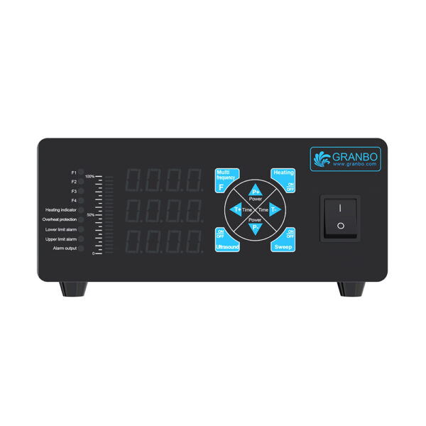
100-300W Digital Ultrasonic Generator 25-135kHz Multiple Frequency Sweep Mode Adjustable Power for Laboratory Instrument Cleaning Tanks
SKU:
GB-G600-I-100-300W
$9,999.00 piece
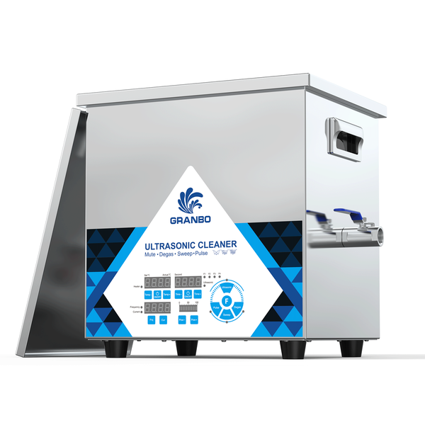
10L 20kHz Low-Frequency Ultrasonic Bath – 0–600W Power with Degas, Sweep & Pulse
SKU:
GNLH0610-20
$735.00 piece
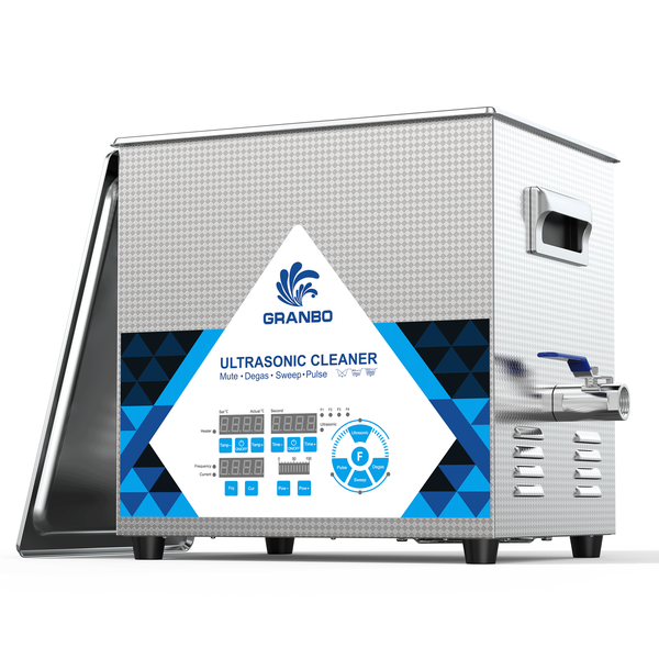
10L 80kHz Benchtop Ultrasonic Cleaner with 400W Adjustable Power for Optical Components & Pipettes
SKU:
GL0810-80
$520.00 piece
Reviews
Clear filtersThere are no reviews yet.