

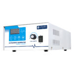
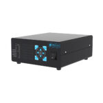
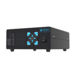
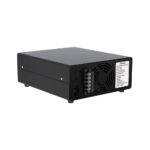
100-300W Digital Ultrasonic Generator 25-135kHz Multiple Frequency Sweep Mode Adjustable Power for Laboratory Instrument Cleaning Tanks
$9,999.00 piece
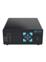
Digital 100-300W ultrasonic generator supports multiple frequencies from 25-135kHz with 0-100% adjustable power and sweep mode for laboratory instrument cleaning tanks.
Shipping & Delivery
-
 Express Air Delivery
Door-to-door with tracking
7-15 Business Days
Calculated at checkout
-
 Standard Ocean Freight
Best for bulk & heavy cargo
25-35 Business Days
Calculated at checkout
-
 Warranty 1 year
-
 Free 30-Day returns
Specification
 Overview
| Model | GB-G600-I-100-300W |
|---|---|
| Brand | Granbo |
| Manufacturer | Granbo Technology Industrial Shenzhen Co., Ltd. |
| Origin | China |
| Frequency | 120kHz, 130kHz, 17kHz, 20kHz, 25kHz, 28kHz, 33kHz, 40kHz, 68kHz, 80kHz |
| Power | 0-300W |
| Power Control | 0–100% NC Adjustable |
| Plate Dimensions (L×W×H) | 220 × 255 × 90 mm |
| Installation Method | Benchtop / External Free-standing |
| Function | Continuous Operation, Digital Control, Heating, Power Adjustable, Timer, Ultrasonic |
| Voltage | 100V-120V ~ 60Hz / 220V-240V ~ 50Hz |
| Ambient Temperature | 0–40℃ |
| Relative Humidity | 40%–90% |
| Net Weight | 3.0 kg |
| Warranty | 1 Year |
| Applications | DIY Ultraonic Cleaner, DIY Ultraonic Machine, DIY Ultrasonic Cleaning Tank |
| Important Notes | This product is highly customized and must be preset at the factory according to your technical specifications prior to shipment. Please contact us to confirm your requirements before ordering; do not place an order directly. |
Packaging
| Chargeable Weight | 1 kg |
|---|---|
| Package Dimensions | 10 × 10 × 9 cm |
Description
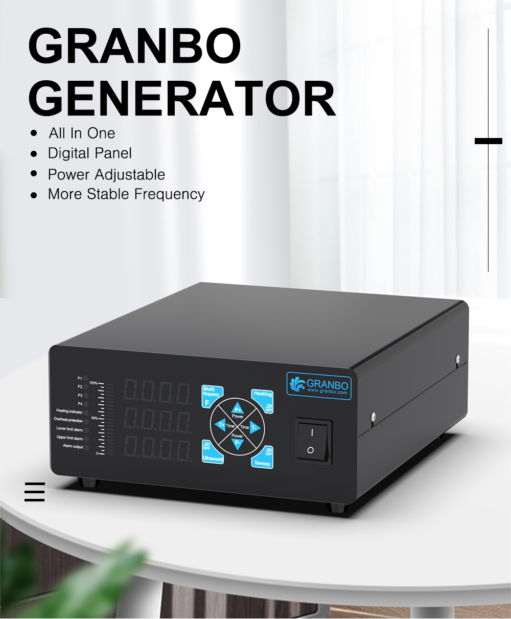
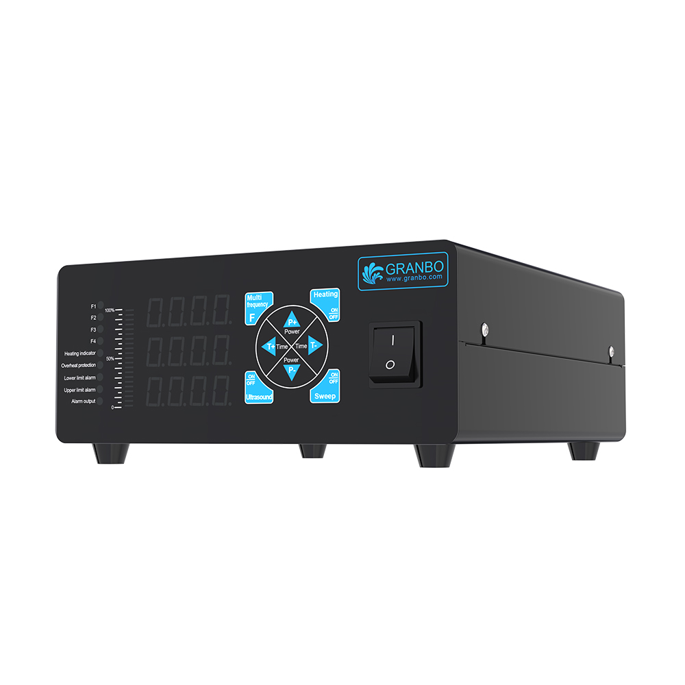
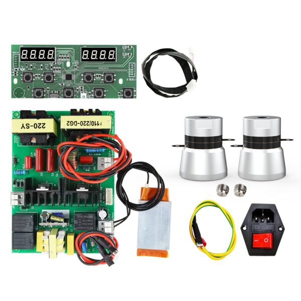
The GRANBO digital ultrasonic generator provides high-stability driving power for industrial and commercial ultrasonic transducer systems. Built as an all-in-one compact unit, it integrates digital numerical power regulation, automatic frequency tracking, multi-mode ultrasonic output, and PLC remote control terminals.
Core Features
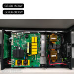
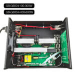
- All-in-One Architecture: Integrates driving circuitry, digital control logic, and cooling components into a single chassis.
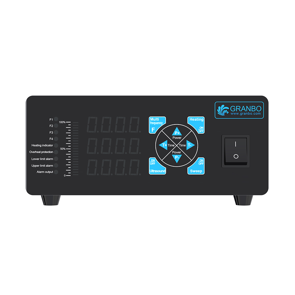
- Digital Display Panel: 3-row LED digital readout displays frequency, operating current, run time, and internal system temperature.
- Numerical Power Control: Power output adjustable from 0% to 100% via front-panel control keys.
- Frequency Stability: Equipped with automatic frequency tracking and wide-band adaptation.
Technical Specifications
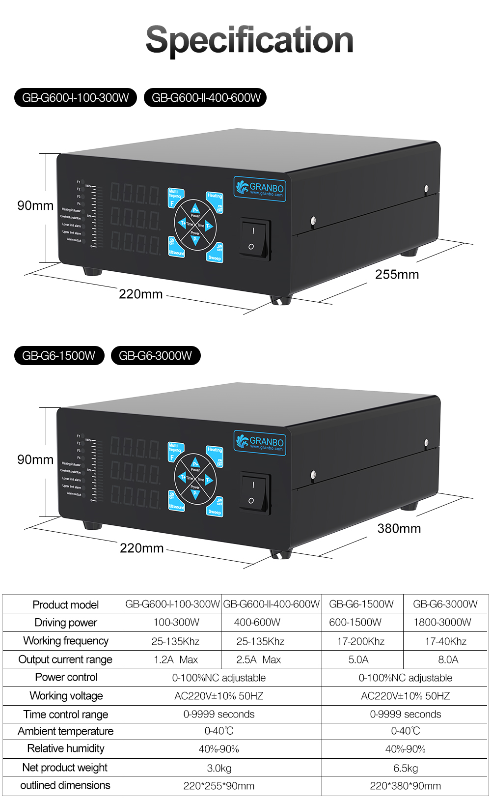
| Model | GB-G600-I-100-300W | GB-G600-II-400-600W | GB-G6-1500W | GB-G6-3000W |
|---|---|---|---|---|
| Driving Power | 100W–300W | 400W–600W | 600W–1500W | 1800W–3000W |
| Operating Frequency | 25 kHz–135 kHz | 25 kHz–135 kHz | 17 kHz–200 kHz | 17 kHz–40 kHz |
| Max Output Current | 1.2A Max | 2.5A Max | 5.0A Max | 8.0A Max |
| Power Control Range | 0%–100% NC adjustable | 0%–100% NC adjustable | 0%–100% NC adjustable | 0%–100% NC adjustable |
| Operating Voltage | 100V-120V ~ 60Hz / 220V-240V ~ 50Hz (configurable by destination region) | 100V-120V ~ 60Hz / 220V-240V ~ 50Hz (configurable by destination region) | 100V-120V ~ 60Hz / 220V-240V ~ 50Hz (configurable by destination region) | 100V-120V ~ 60Hz / 220V-240V ~ 50Hz (configurable by destination region) |
| Timer Setting Range | 0–9999 seconds | 0–9999 seconds | 0–9999 seconds | 0–9999 seconds |
| Ambient Temperature | 0°C to 40°C | 0°C to 40°C | 0°C to 40°C | 0°C to 40°C |
| Operating Humidity | 40%–90% RH | 40%–90% RH | 40%–90% RH | 40%–90% RH |
| Net Weight | 3.0 kg | 3.0 kg | 6.5 kg | 6.5 kg |
| External Dimensions | 220 x 255 x 90 mm | 220 x 255 x 90 mm | 220 x 380 x 90 mm | 220 x 380 x 90 mm |
Compatible Equipment
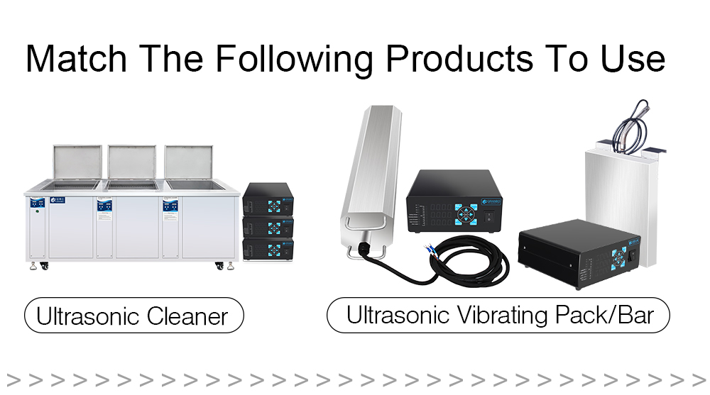
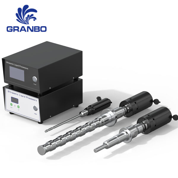
The generator matches standard industrial ultrasonic systems, including:
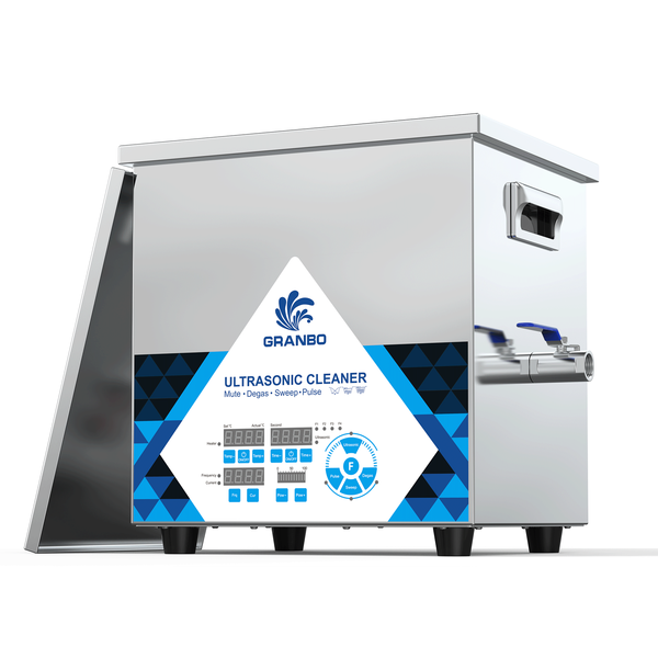
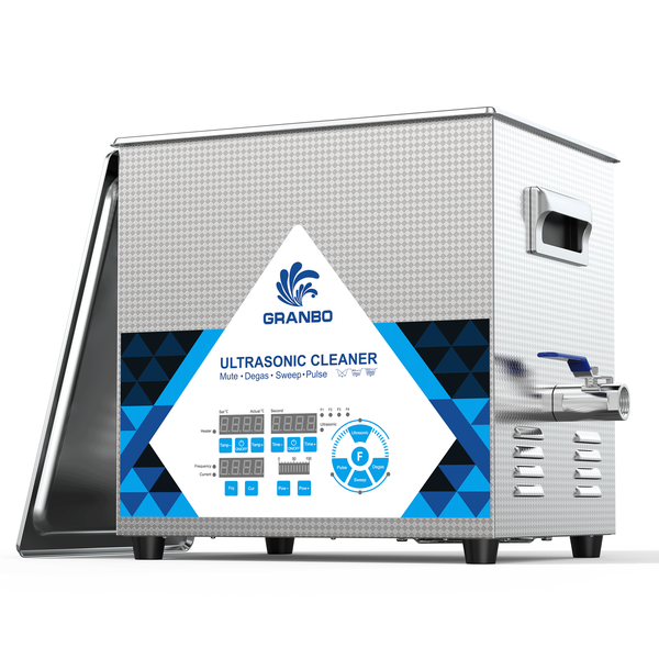
- Ultrasonic Cleaners: Multi-tank or single-tank benchtop and industrial wash stations.
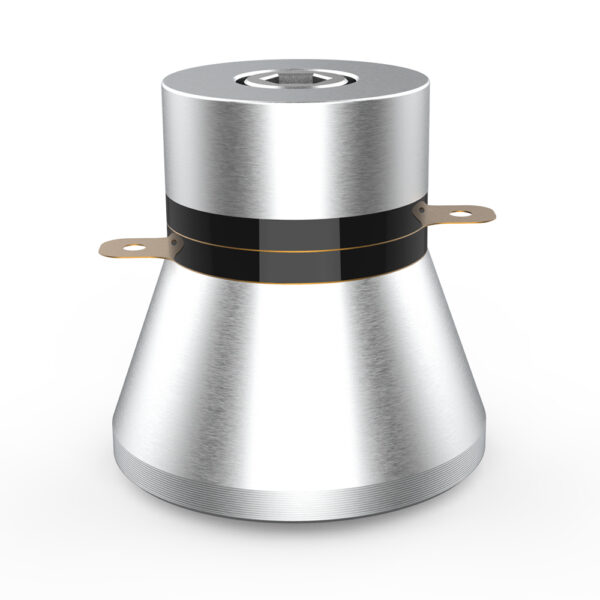
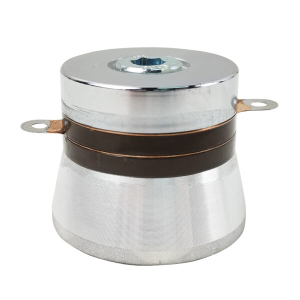
- Ultrasonic Immersible Transducer Packs: Submersible transducer boxes for retrofit tanks.
- Ultrasonic Transducer Bars: Tubular transducer systems for pipeline and targeted immersion processing.
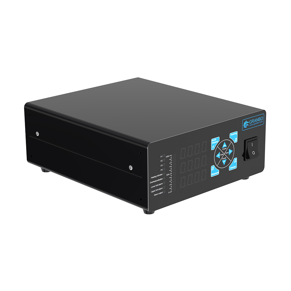
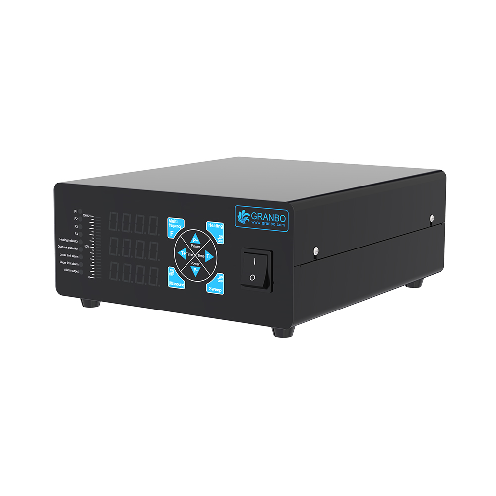
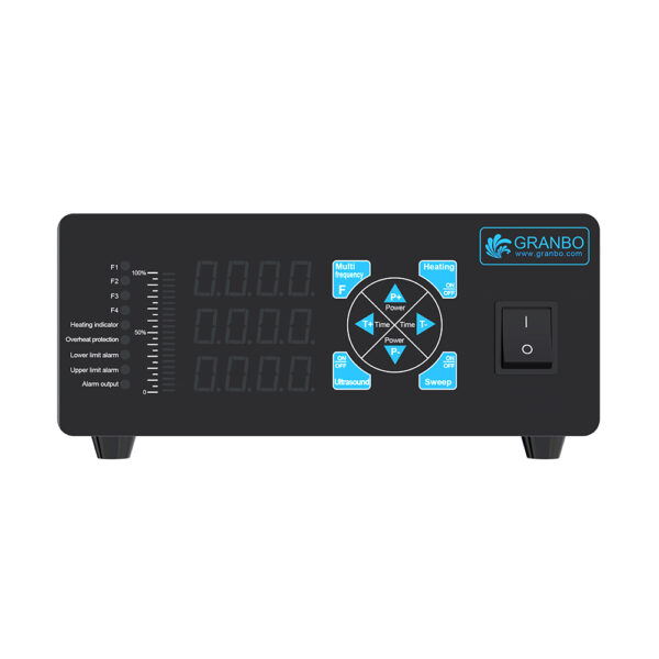
Operation Panel & Interface Layout
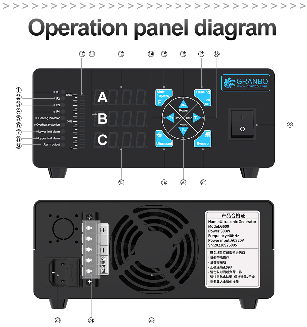
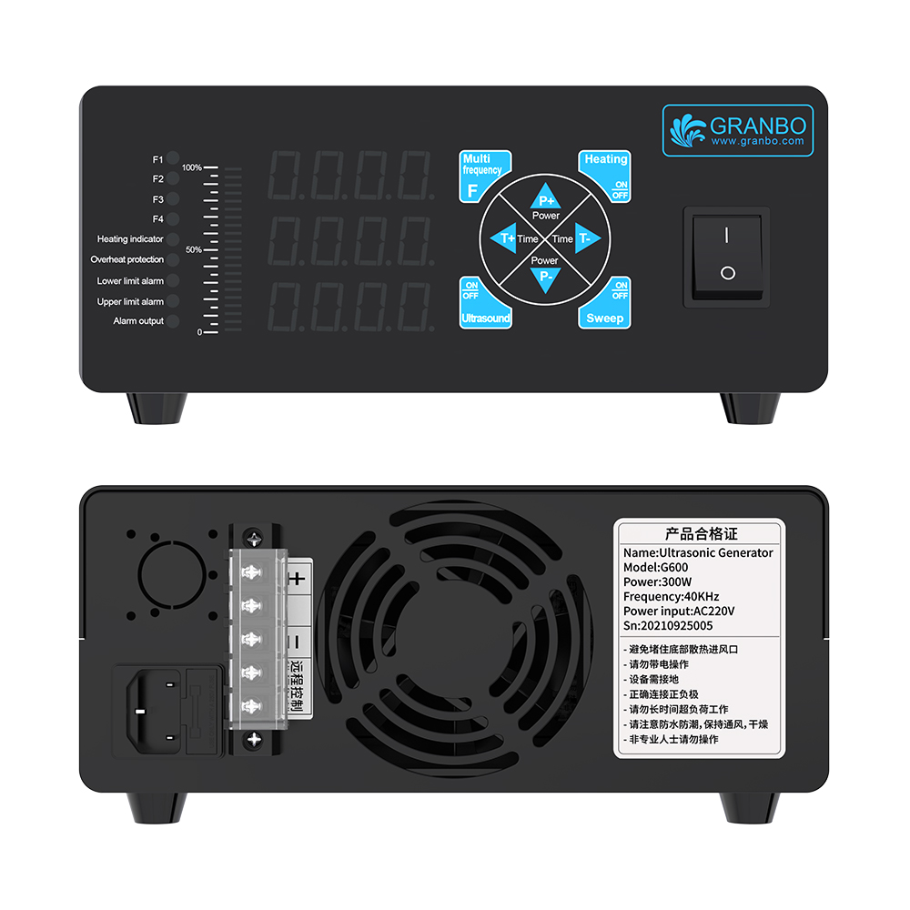
Front Panel Indicators and Keys
- (1) F1: Frequency band 1 active indicator
- (2) F2: Frequency band 2 indicator (customization required)
- (3) F3: Frequency band 3 indicator (customization required)
- (4) F4: Frequency band 4 indicator (customization required)
- (5) Heating Indicator: Heating status light (flashing indicates active heating)
- (6) Overheat Protection Indicator: Fault light (illuminates above 70°C internal temperature)
- (7) Lower Limit Alarm Indicator: Current under-load alarm indicator
- (8) Upper Limit Alarm Indicator: Current over-load alarm indicator
- (9) Alarm Output Indicator: General hardware fault alarm indicator
- (10) Power Indicator Bar: 0% to 100% LED output level scale
- (11) Display Window B: Real-time operating current readout (A)
- (12) Display Window A: Operating frequency (kHz) or system status code
- (13) Display Window C: Countdown timer or accumulated operational runtime (seconds)
- (14) T+ Key: Increases set time; switches Display A to show real-time internal temperature
- (15) F Key: Multi-frequency band toggle (customization required)
- (16) P+ Key: Increases output power percentage
- (17) Heating Key: Toggles heating circuit ON/OFF (customization required)
- (18) T- Key: Decreases set time
- (19) ON/OFF Key: Powers ultrasound output ON/OFF
- (20) P- Key: Decreases output power percentage
- (21) Sweep Key: Frequency sweep toggle switch
- (22) Power Switch: Main AC power switch (I / O)
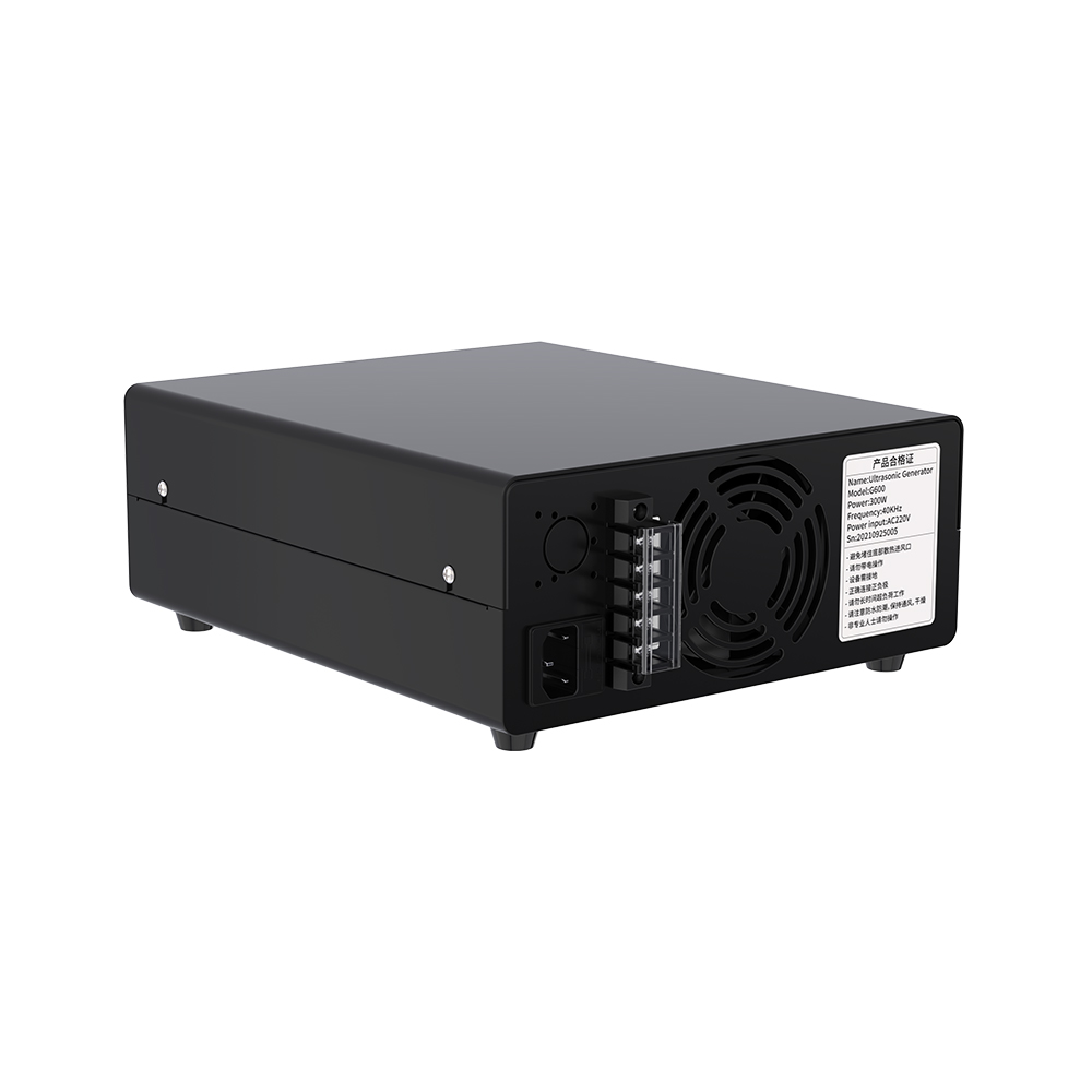
Rear Panel Interface
- (23) Power Supply Socket: Standard AC power inlet
- (24) Output Terminal Block:
+: Ultrasound positive output terminal-: Ultrasound negative output terminalRemote Control: PLC system dry contact control terminals
- (25) Cooling Fan: Forced-air exhaust cooling fan
Operating Modes and Display States
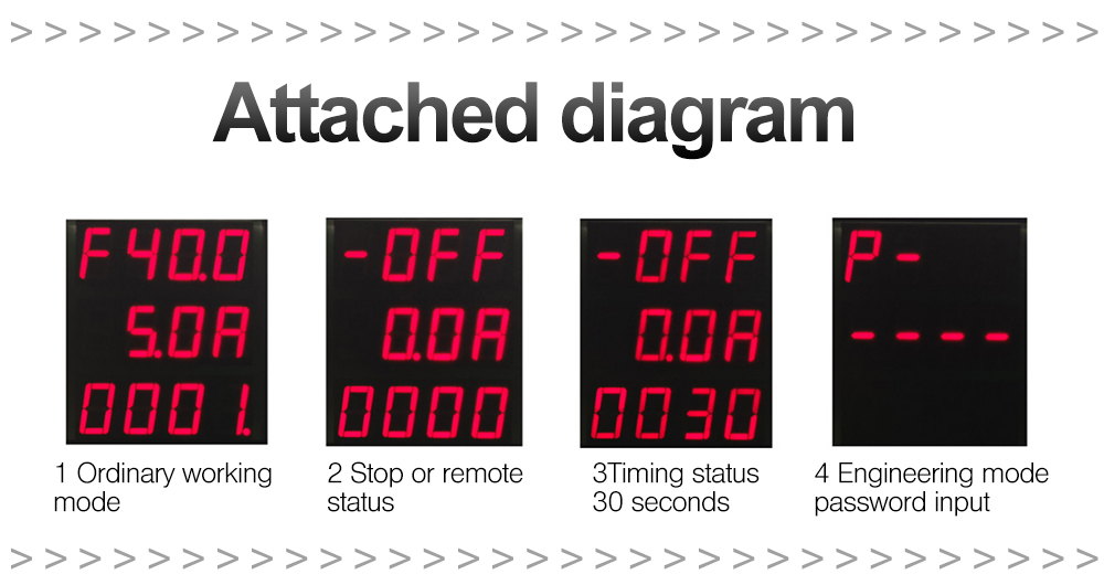
The 3-row LED digital panel displays operational statuses:
- Status 1 (Standard Working Mode): Window A displays operating frequency (e.g.,
F40.0), Window B displays operating current (e.g.,5.0A), Window C displays current runtime (e.g.,0001). - Status 2 (Stop / Remote Standby Mode): Window A displays
[-OFF], Window B displays0.0A, Window C displays0000. - Status 3 (Timer Setting Mode): Window A displays
[-OFF], Window B displays0.0A, Window C displays set countdown duration (e.g.,0030for 30 seconds). - Status 4 (Engineering Parameter Mode): Window A displays
P-, Window B displays password entry prompt----.
Functional Instructions & Configuration
1. Power Output Setting
Under working conditions, press [P+] or [P-] to increase or decrease output power. The LED bar graph displays the corresponding power percentage from 0% to 100%.
2. Frequency Sweep Mode
During operation, press [Sweep] to enter frequency sweep mode. Press [Sweep] again to exit. (Note: Sweep mode increases mechanical stress on transducers; use as appropriate).
3. Timer Setting and Cancellation
During operation, press [ON/OFF] until Display Window [A] displays [-OFF]. Press [T+] or [T-] to adjust the target duration in Window [C] (e.g., 0030 indicates 30 seconds). Press [ON/OFF] to begin timed countdown operation. When Window [C] reaches 0, timer mode terminates.
4. Internal Temperature Inspection
During operation, press [T+]. Display Window [A] displays the internal machine temperature in degrees Celsius for 3 seconds before automatically returning to the frequency display.
5. Remote Control Mode Configuration
With the main power switch turned off, press and hold [T+] while turning on the main power switch. Hold [T+] for 2 seconds, then release. Window [A] displays [-OFF], confirming remote control mode is active. Repeat this procedure to exit remote mode.
6. Remote Control Terminal Wiring
In remote mode, use an independent dry contact switch across the rear remote terminals. Closing the contact starts ultrasonic operation; opening the contact stops ultrasonic output. This interface supports multi-unit synchronized control.
7. Operating Frequency Calibration
During operation, press and hold [Sweep] and [ON/OFF] simultaneously for 5 seconds. The frequency value in Window [A] flashes continuously. Press [P+] and [P-] to adjust the frequency. Press and hold [Sweep] and [ON/OFF] simultaneously for 5 seconds to exit and save.
In stop status, follow the same procedure to switch frequency bands (25 kHz, 28 kHz, 40 kHz). (Note: Matching inductors and transformer taps must be adjusted when changing frequency bands).
8. Maximum Current Setting
In stop status (Window [A] displaying [-OFF]), press and hold [Sweep] for 5 seconds. The current value in Window [B] flashes continuously. Press [P+] and [P-] to adjust the maximum current value. Press and hold [Sweep] for 5 seconds to exit.
9. One-Key Intelligent Frequency Tracking
During operation, press and hold [ON/OFF] for 5 seconds to start intelligent tracking. Display Window [A] flashes continuously while the system scans and locks resonance frequency. Once tracking completes, Window [A] stops flashing and resumes normal display.
10. Ultrasonic Cleaning Mode Selection
In stop status, press and hold [Sweep] and [T-] simultaneously for 5 seconds until Window [B] flashes continuously. Press [P+] and [P-] to select the operating mode:
00: Concentrated mode02: Standard mode03: Coarse wash mode08: Fine wash mode
Press and hold[Sweep]and[T-]simultaneously for 5 seconds to confirm and exit.
11. Engineering Mode Access
In stop status, press and hold [Sweep] and [P-] simultaneously for 5 seconds. When the password prompt appears (P- ----), press [P+], [P-], [T+], and [T-] to enter password 9876. Press [Sweep] to confirm entry into engineering parameters.
12. Operational Status Identification
- Mode Verification: Upon startup, if Window [A] displays a frequency value, standard local mode is active; if Window [A] displays
[-OFF], remote control mode is active. - Timer Mode: If Window [C] displays a value between
0001and9999, countdown timing mode is active. - Auto-Matching Status: If Window [C] displays
[SOU], automatic matching status is active.
(Note: After all key operations are completed, the display flashes after 10 seconds of inactivity to save current settings automatically).
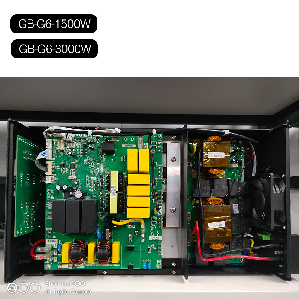
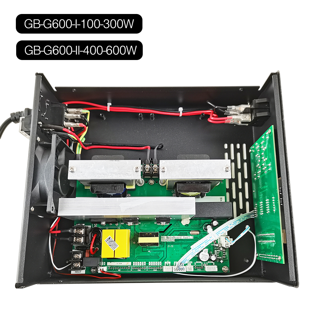
Internal Layout & Construction
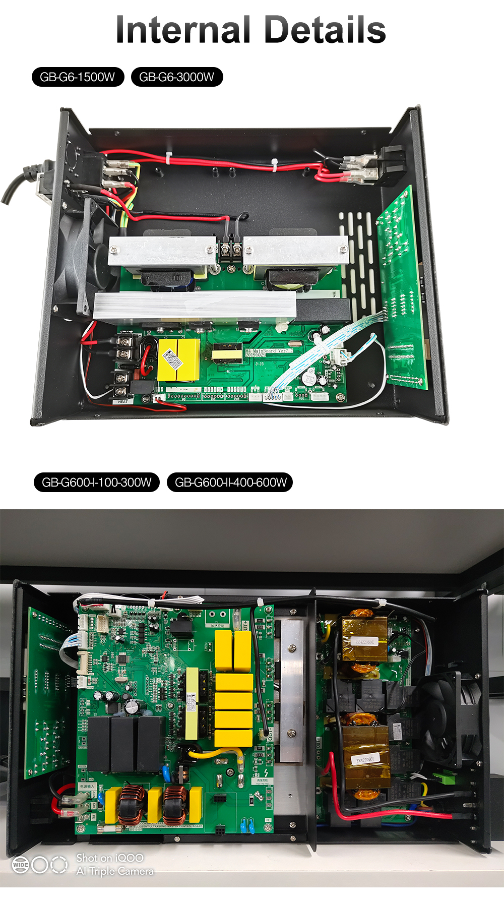
Physical Product Dimensions and Enclosure Views
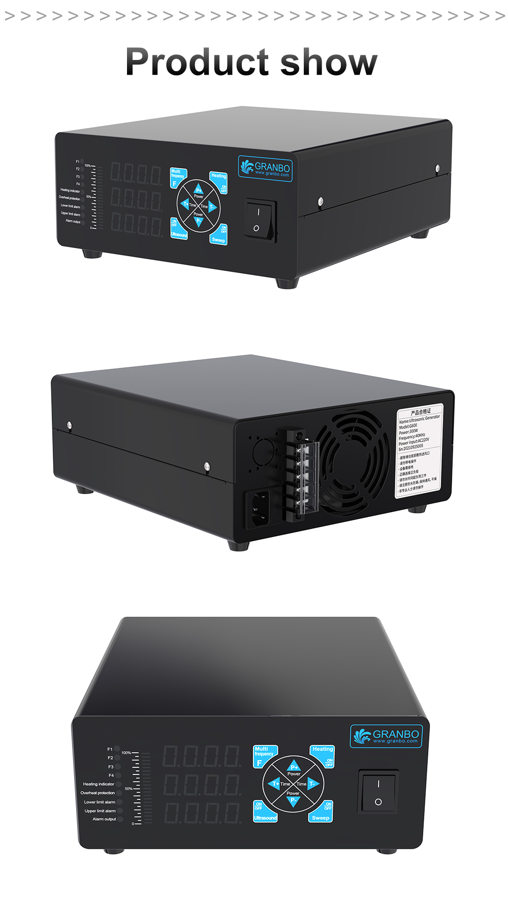
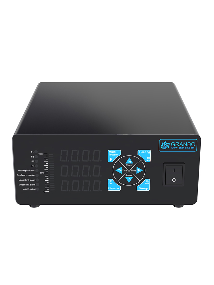
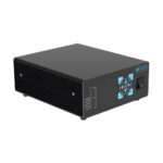
The chassis design incorporates non-slip chassis support feet, recessed front controls, rear-mounted ventilation grills, and standard industrial terminal isolation covers.
Manufacturing and Quality Assurance
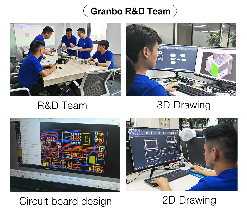
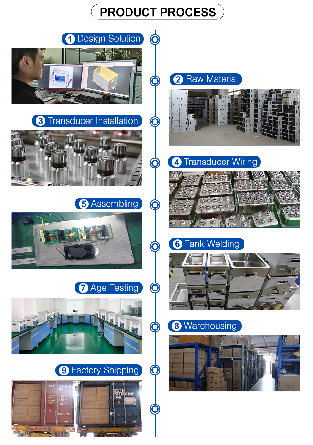
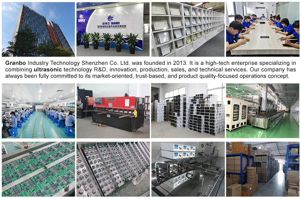
Granbo Industry Technology Shenzhen Co. Ltd., established in 2013, handles in-house electronic circuit board design, 2D sheet metal engineering, and 3D structural modeling. Production follows a standard 9-stage manufacturing flow:
- Design Solution & Schematic Engineering
- Raw Material & Enclosure Staging
- Transducer Installation & Matching
- Transducer Harness Wiring
- Internal PCB & Component Assembling
- Tank Structure Welding
- Burn-In & Age Testing
- Warehousing Inspection
- Factory Shipping & Freight Packing
Customer Reviews
You must be logged in to post a review.
Reviews
Clear filtersThere are no reviews yet.