

100W Digital Controller Ultrasonic Cleaner Circuit Board with Heater Driver PCB for Transducer System DIY Parts and Tank Repair
$1,400.00 piece
This 100W ultrasonic cleaner circuit board features a digital controller and heater driver. Built for stable output, easy setup, and cost-effective tank repair.
Shipping & Delivery
-
 Express Air Delivery
Door-to-door with tracking
7-15 Business Days
Calculated at checkout
-
 Standard Ocean Freight
Best for bulk & heavy cargo
25-35 Business Days
Calculated at checkout
-
 Warranty 1 year
-
 Free 30-Day returns
Specification
 Overview
| Model | DG2-S100 |
|---|---|
| Brand | Granbo |
| Manufacturer | Granbo Technology Industrial Shenzhen Co., Ltd. |
| Origin | China |
| Frequency | 40kHz |
| Power | 100W |
| Voltage | 100V-120V ~ 60Hz / 220V-240V ~ 50Hz |
| Warranty | 1 Year |
| Applications | DIY Ultraonic Cleaner, DIY Ultraonic Machine, DIY Ultrasonic Cleaning Tank |
Packaging
| Chargeable Weight | 65.4 kg |
|---|---|
| Package Dimensions | 75 × 45 × 53 cm |
Description
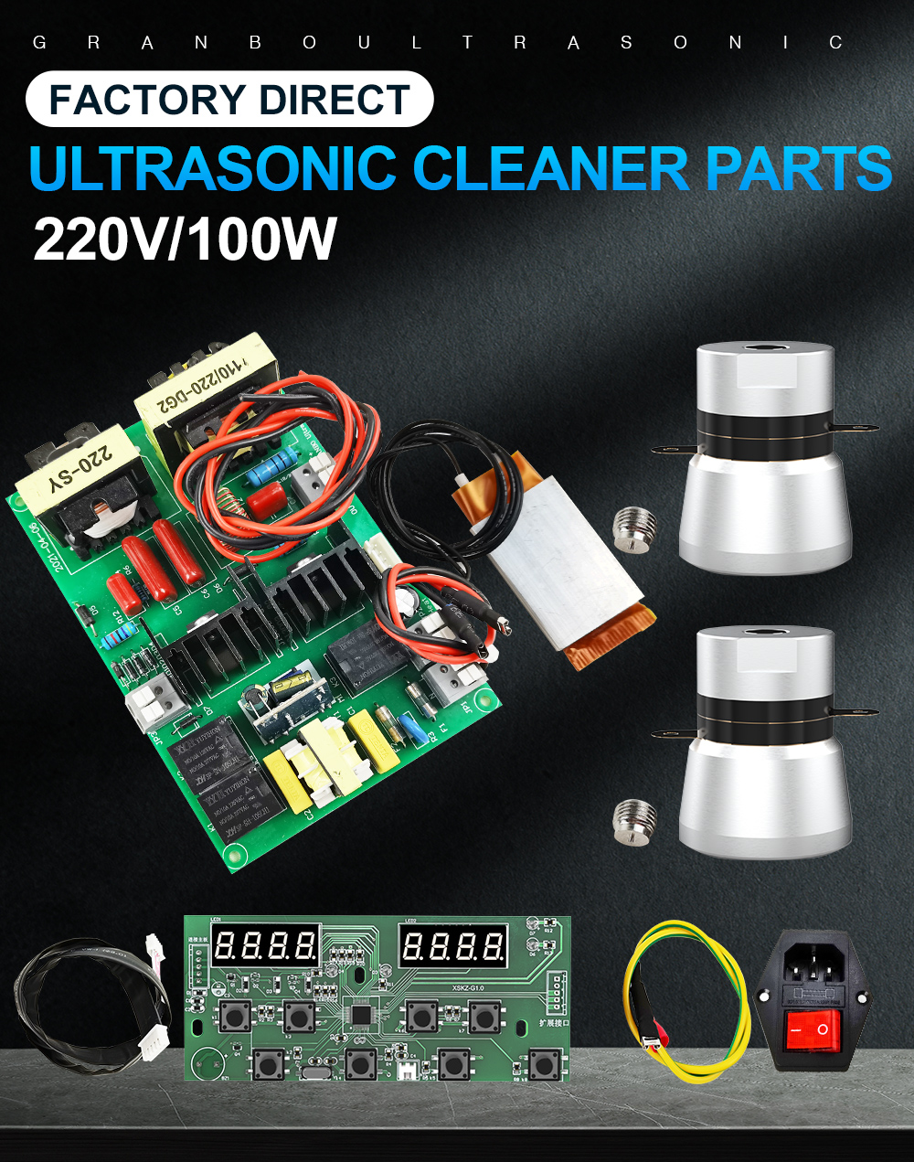
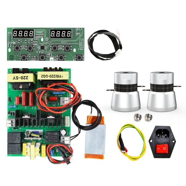
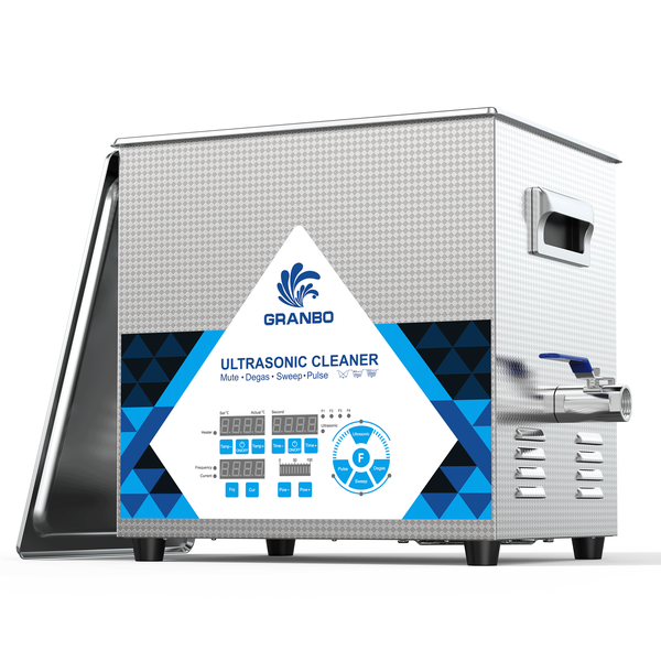
This ultrasonic cleaner DIY conversion and repair kit provides core drive electronics, dual transducers, a heating element, and a digital controller. It is designed for building custom ultrasonic cleaning tanks or replacing damaged circuits in existing units.
- Input Voltage: 100V–120V ~ 60Hz / 220V–240V ~ 50Hz
(Units are dispatched configured to match destination country standards. Specific voltage requirements can be specified in order remarks). - Key Features:
- High-quality components for reliable performance
- Easy installation for convenience
- Customizable for personalized cleaning solutions
- Improved cleaning efficiency for professional-grade results
- Cost-effective compared to buying a new ultrasonic cleaner
Package Contents
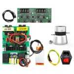
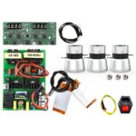
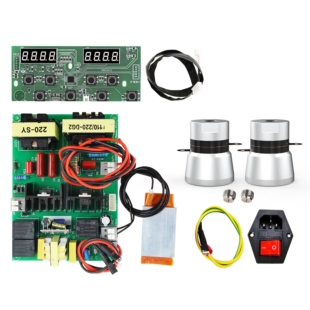
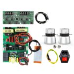
- 1 x Ultrasonic Generator Driver Circuit Board
- 1 x Digital Display & Control Board
- 1 x Multi-pin Ribbon Cable (Driver to Display)
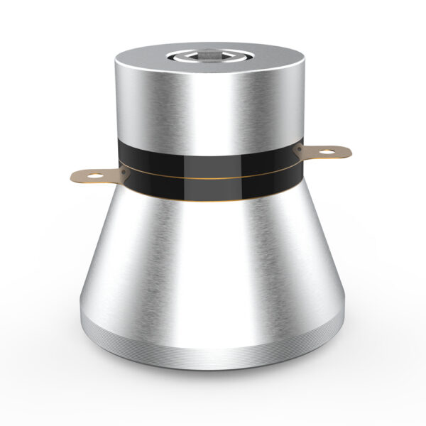
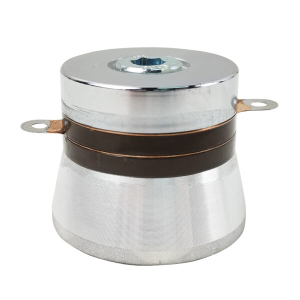
- 2 x 50W 40kHz Ultrasonic Horn Transducers (100W total acoustic power)
- 2 x Mounting Studs
- 1 x Heating Plate
- 1 x Switched AC Power Socket with Fuse Compartment
- 1 x Grounding Wire
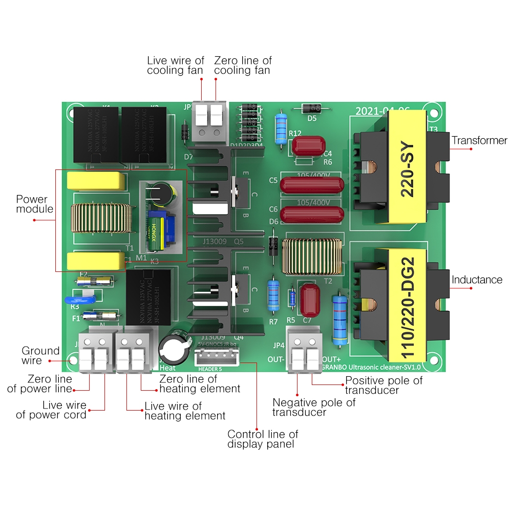
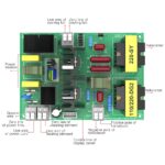
Driver Circuit Board Terminal Guide
- AC Input (Power Cord): Live (L) and Neutral (N) screw terminals
- Ground: Dedicated chassis earth terminal
- Heating Element: Live (PTC / Live) and Neutral (N) screw terminals marked
Heat - Transducer Output: High-frequency output terminals marked
OUT+(Positive) andOUT-(Negative) - Cooling Fan Output (JP3): Live and Neutral terminals for external cooling fan connection
- Display Connection (HEADER 5): 5-pin port for digital display control cable
- Key On-Board Components: Integrated power module, dual switching transistors on heat sink, matching inductor (110/220-DG2), and power transformer (220-SY)
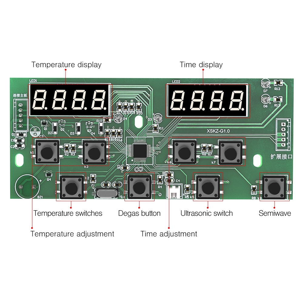
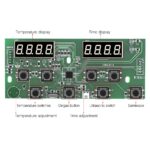
Digital Control Panel Layout & Functions
- Temperature Display (LED1): 4-digit numeric readout for actual and set temperature values
- Time Display (LED2): 4-digit numeric readout for countdown timer and cycle settings
- Temperature Switches: Toggles tank heating on and off
- Temperature Adjustment: Increments and decrements target solution temperature
- Ultrasonic Switch: Activates and deactivates ultrasonic cavitation
- Time Adjustment: Sets cleaning duration
- Degas Button: Initiates intermittent pulse cycle to remove dissolved gases from fluid
- Semiwave: Activates half-wave power mode for gentle cleaning of sensitive items
- Board Dimensions: 143.5 mm length x 61 mm width
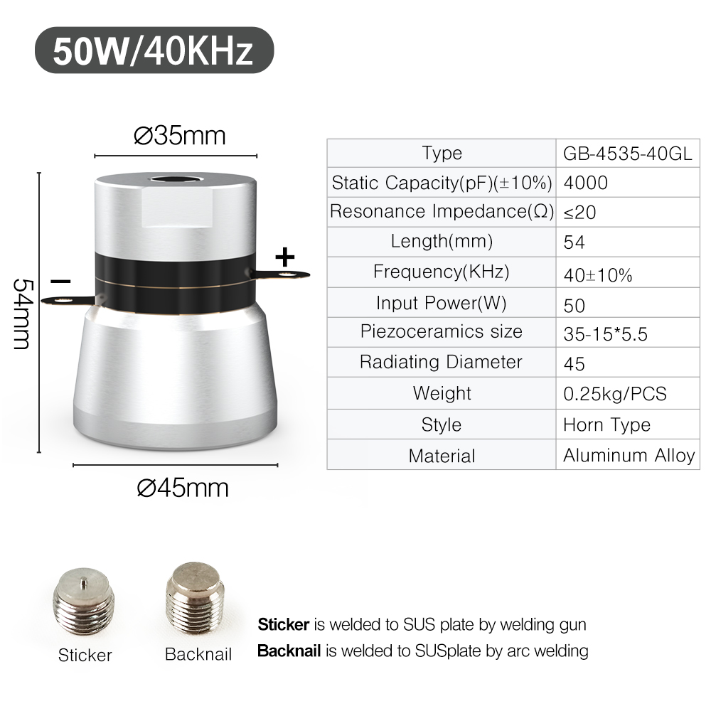
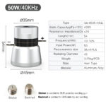
Transducer Specifications
- Model: GB-4535-40GL
- Style: Horn Type
- Operating Frequency: 40 ± 10% kHz
- Input Power: 50W (per unit)
- Static Capacitance: 4000 ± 10% pF
- Resonance Impedance: ≤ 20 Ω
- Piezoceramic Element Dimensions: 35 mm x 15 mm x 5.5 mm
- Top Diameter: Ø35 mm
- Radiating Face Diameter: Ø45 mm
- Overall Height: 54 mm
- Unit Weight: 0.25 kg
- Construction Material: Aluminum Alloy
System Wiring Instructions
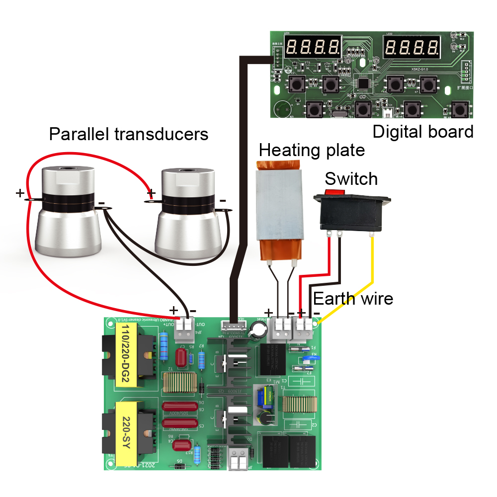
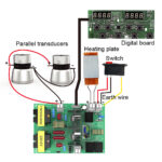
- Connect the multi-pin ribbon cable between
HEADER 5on the driver board and the digital control panel. - Connect the switched AC inlet to the board’s power input terminals: Live (
L) and Neutral (N). Connect the green/yellow grounding wire to the stainless steel chassis. - Connect the heating element leads to the terminal block marked
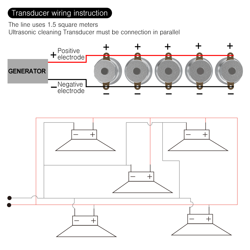
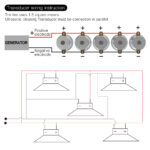
Heat. - Connect the two ultrasonic transducers in parallel: connect both transducer positive terminals (+) to
OUT+, and both negative terminals (-) toOUT-.
- Wiring Gauge: Transducer connections must use 1.5 mm² wire.
- Transducer Polarity: All transducers must be connected in parallel. Never connect transducers in series.
Instructions for Wiring Between Circuit Board and Transducer
- The circuit board cannot be powered on without load.
- After installation, it is better not to start the machine for more than 1 minute without any cleaning fluid.
- The 60W drive board is one transducer and is connected to the terminal of the circuit board. One circuit board and one transducer are used together.
- The 120W drive board is two transducers and is connected to the terminal of the circuit board. One circuit board and two transducers are used together.
- The 180W drive board is three transducers and is connected to the terminal of the circuit board. One circuit board and three transducers are used together.
- OUT + is connected to the positive pole of the transducer, OUT – is connected to the negative pole of the transducer. The power supply L of the drive board is positive (Live) and N is negative (Neutral). Parallel drive plate Lb is positive and Nb is negative. Heating PTC is positive and N is negative. The display board HT is the interface and the display board J1 is the temperature probe interface. Remember not to get it wrong.
(Note: The voltage at the output terminal of the circuit board is about 400V. Pay attention to safety. It is best to have a leakage protection switch on the input power supply to ensure safety!)
Transducer Installation & Stud Welding Instructions
- Mounting Stud Options:
- Sticker Stud: Welded to the stainless steel (SUS) plate with a stud welding gun.
- Backnail Stud: Welded to the SUS plate via arc welding.
- Mounting Procedures:
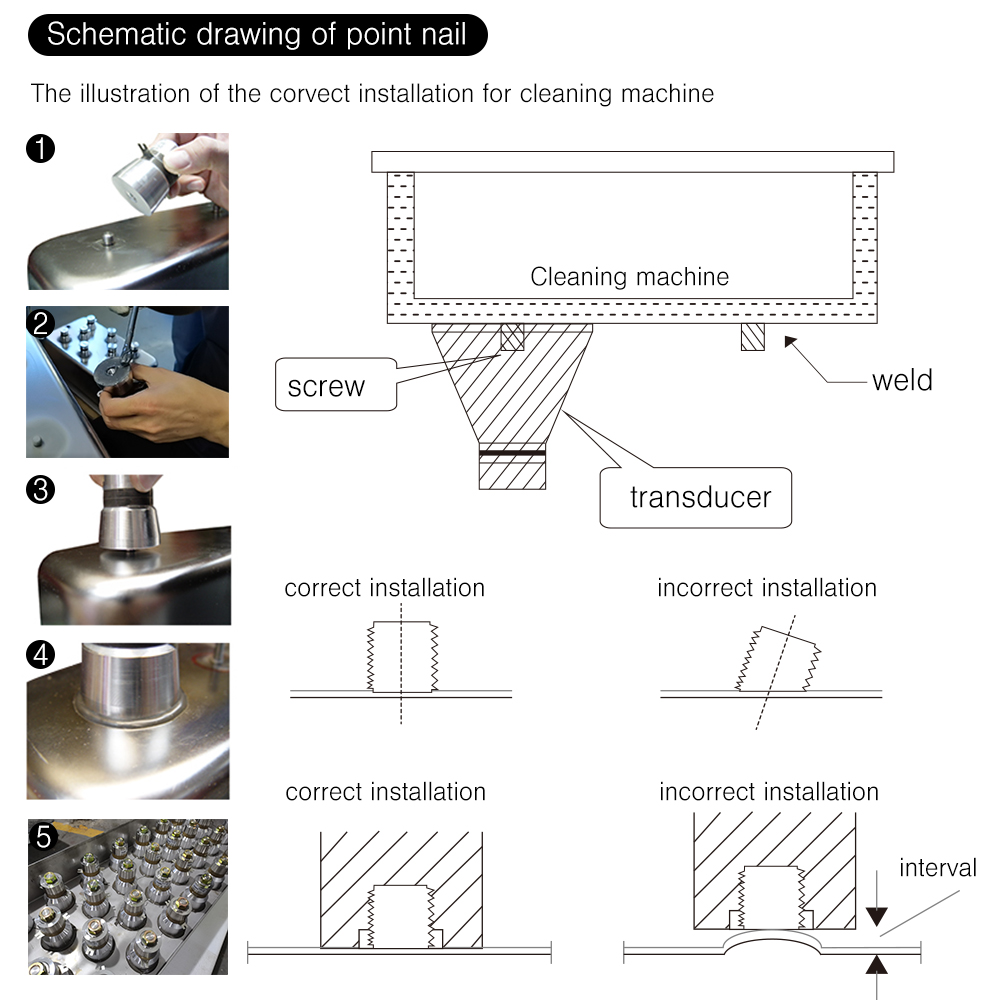
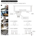
- Ensure the welding stud is perpendicular to the base plate. Tilted studs prevent uniform surface contact.
- The tank plate must remain completely flat without indentation or deformation at the weld joint.
- Apply specialized adhesive evenly over the contact base, then screw the transducer tightly down to the tank bottom.
- Ensure zero gap or interval exists between the radiating horn face and the cleaning tank surface.
Customer Reviews
You must be logged in to post a review.

Reviews
Clear filtersThere are no reviews yet.