

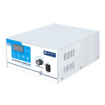
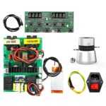
Digital Degas 50W Ultrasonic Cleaner Circuit Board DIY Transducer Driver PCB Spare Parts for Ultrasonic Bath and Tank Cleaning Systems
$1,400.00 piece
Upgrade your equipment with this 50W digital degas ultrasonic cleaner circuit board. It delivers stable power, simple installation, and cost-effective performance.
Shipping & Delivery
-
 Express Air Delivery
Door-to-door with tracking
7-15 Business Days
Calculated at checkout
-
 Standard Ocean Freight
Best for bulk & heavy cargo
25-35 Business Days
Calculated at checkout
-
 Warranty 1 year
-
 Free 30-Day returns
Specification
 Overview
| Model | DG1-S50 |
|---|---|
| Brand | Granbo |
| Manufacturer | Granbo Technology Industrial Shenzhen Co., Ltd. |
| Origin | China |
| Frequency | 40kHz |
| Power | 50W |
| Voltage | 100V-120V ~ 60Hz / 220V-240V ~ 50Hz |
| Warranty | 1 Year |
| Applications | DIY Ultraonic Cleaner, DIY Ultraonic Machine, DIY Ultrasonic Cleaning Tank |
Packaging
| Chargeable Weight | 65.4 kg |
|---|---|
| Package Dimensions | 75 × 45 × 53 cm |
Description
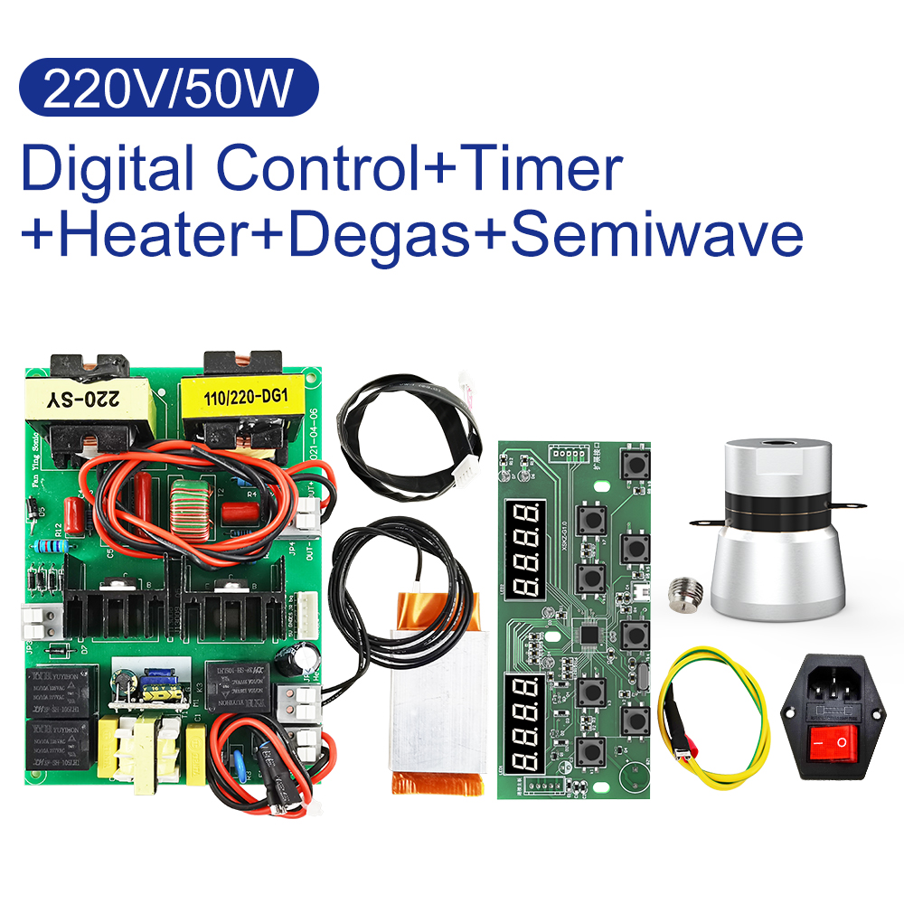
This ultrasonic cleaning circuit board kit provides the core electronics and components for assembling or repairing digital ultrasonic cleaners. It features integrated digital timer and temperature controls, a dedicated degassing cycle, and a semi-wave cleaning mode for sensitive items.
- Input Voltage: 100V–120V ~ 60Hz / 220V–240V ~ 50Hz
(Units ship configured for destination country power standards. Voltage preferences can be specified in order remarks).
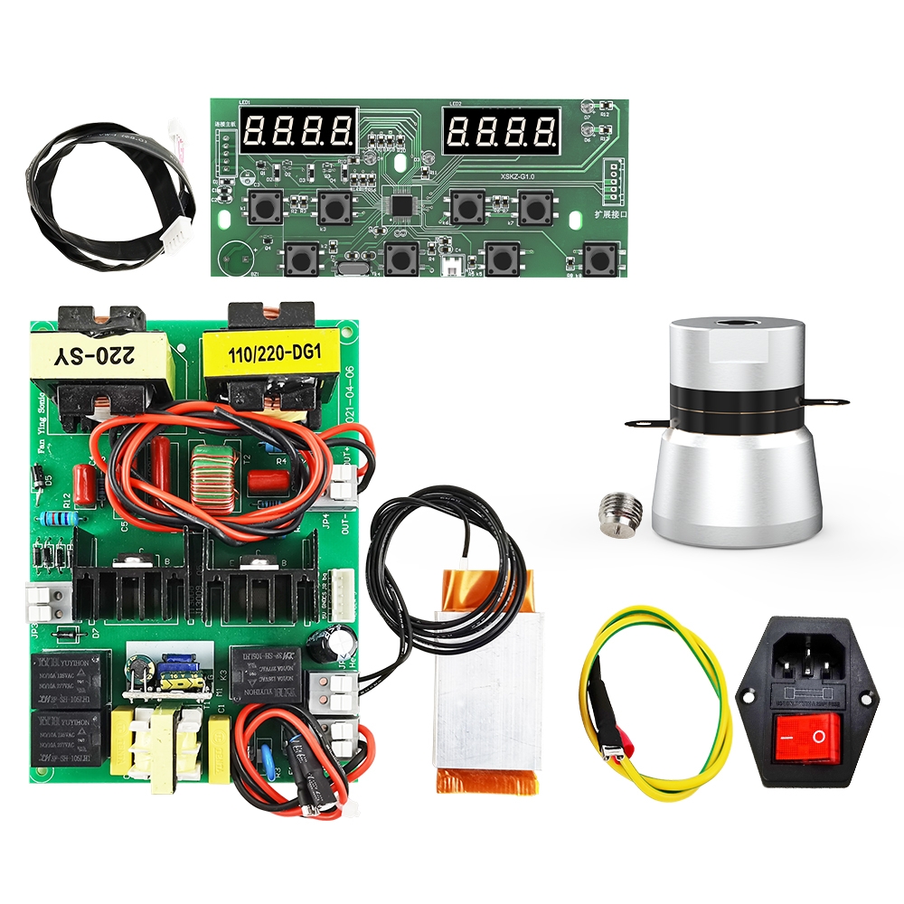
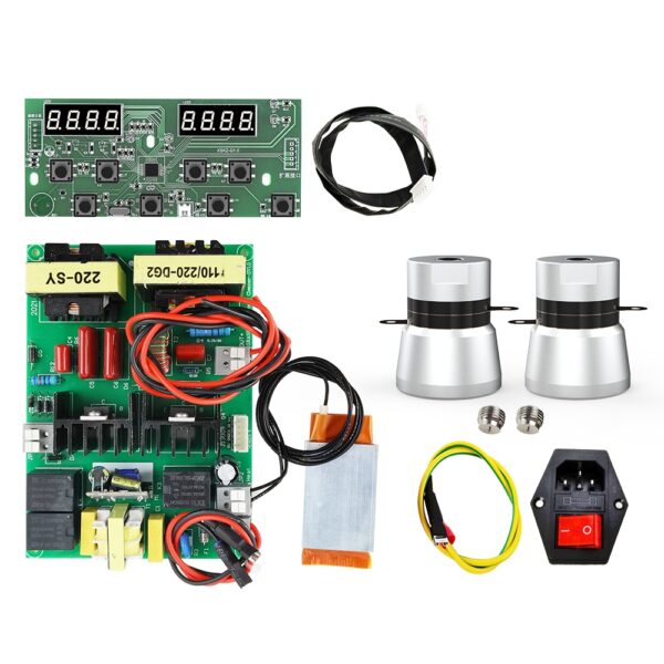
Kit Components
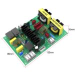
- 1 x Ultrasonic Digital Generator / Driver Circuit Board
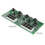
- 1 x Digital Display & Control Panel
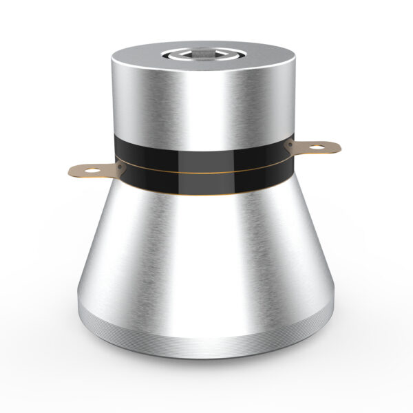
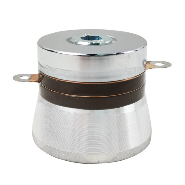
- 1 x 50W 40kHz Horn-Type Ultrasonic Transducer with Mounting Stud
- 1 x 150W PTC Heating Element
- 1 x Switched AC Power Socket with Fuse
- 1 x Grounding Cable
- 1 x Multi-Pin Control Ribbon Cable
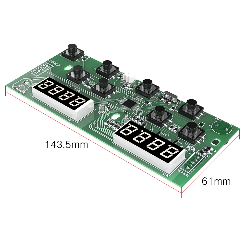
Digital Control Panel & Functions
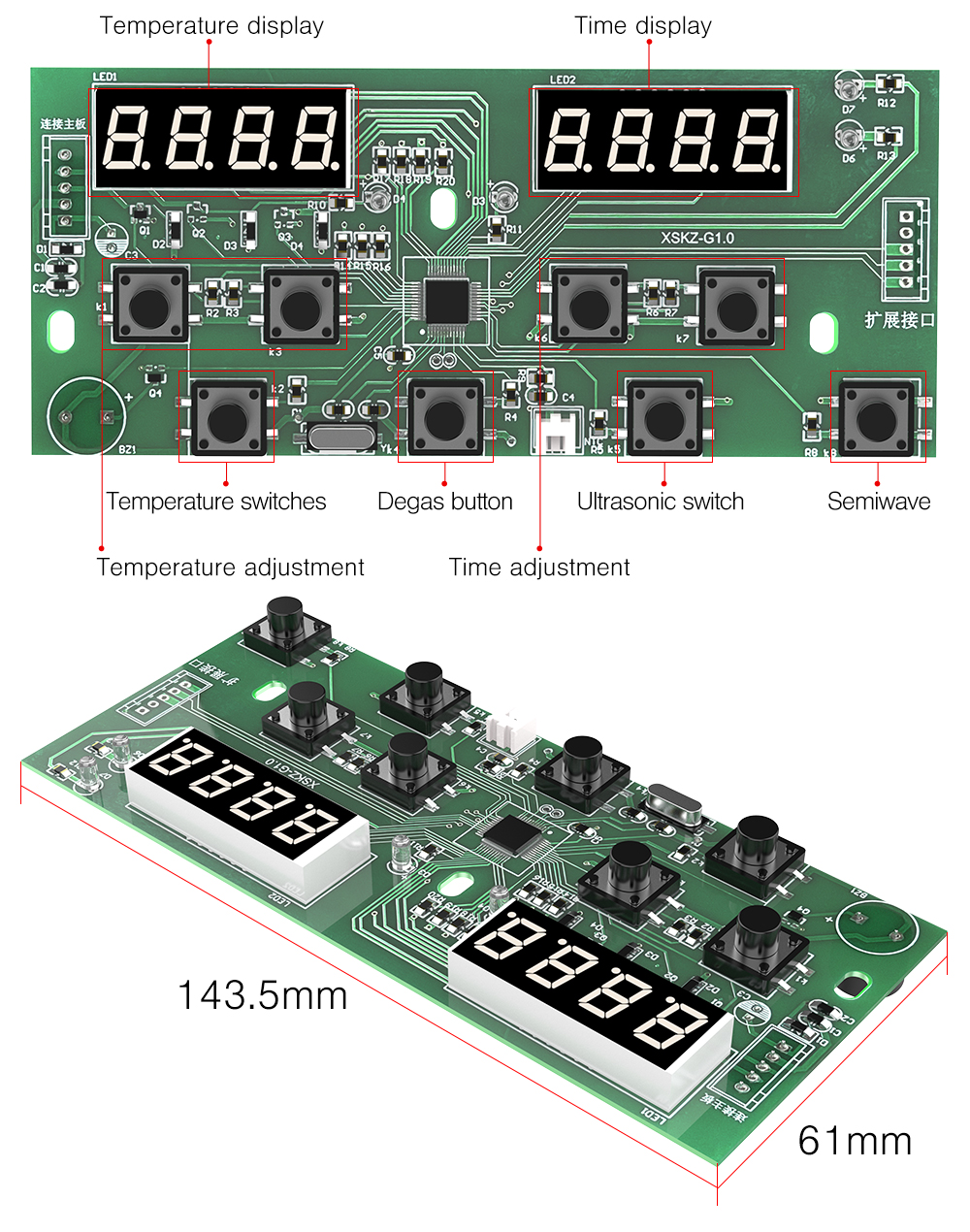
The control panel provides real-time monitoring and parameter adjustment via dual 4-digit LED readouts and tactile function switches:
- Temperature Display (LED1): Shows real-time solution temperature and set target temperature.
- Time Display (LED2): Shows remaining operating duration and timer presets.
- Temperature Adjustment: Sets solution heating temperature.
- Temperature Switches: Enables or disables the heating circuit.
- Time Adjustment: Increases or decreases operating cycle time.
- Ultrasonic Switch: Starts or stops ultrasonic cavitation.
- Degas Button: Cycles ultrasonic power on and off to eliminate trapped gas bubbles from cleaning fluids.
- Semiwave: Activates half-wave power mode for gentle cleaning of fragile parts.
- Panel Dimensions: 143.5 mm x 61 mm
Technical Specifications
Digital Drive Circuit Board
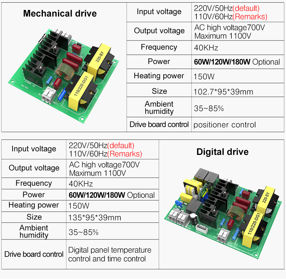
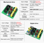
- Input Voltage: 220V/50Hz (Standard) / 110V/60Hz (Available upon remark)
- Output Voltage: AC High Voltage 700V (Maximum 1100V)
- Operating Frequency: 40 kHz
- Ultrasonic Output Power: 60W / 120W / 180W (Optional driver power variants)
- Heating Power: 150W
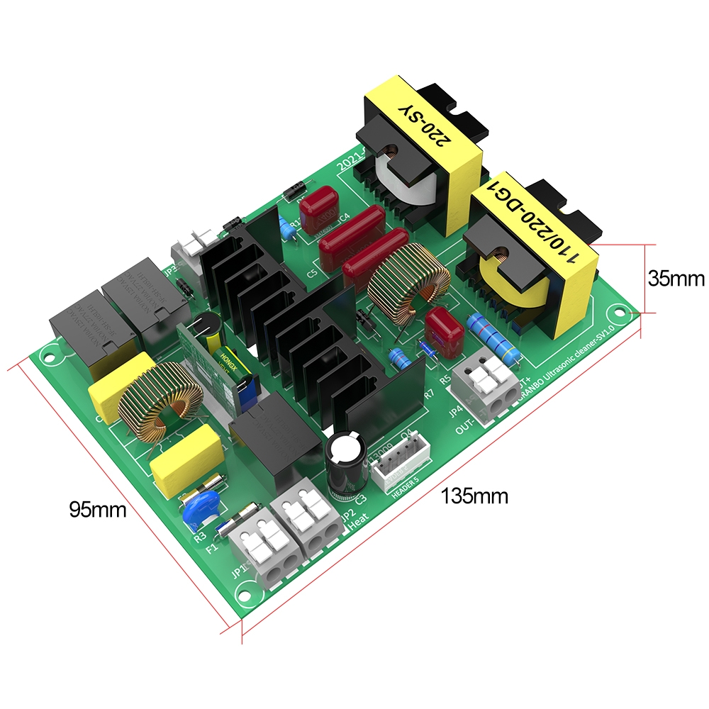
- Board Dimensions: 135 mm x 95 mm x 39 mm (PCB component clearance height: 35 mm)
- Operating Humidity Range: 35%–85% RH
- Control Method: Digital panel temperature and time control
Ultrasonic Transducer
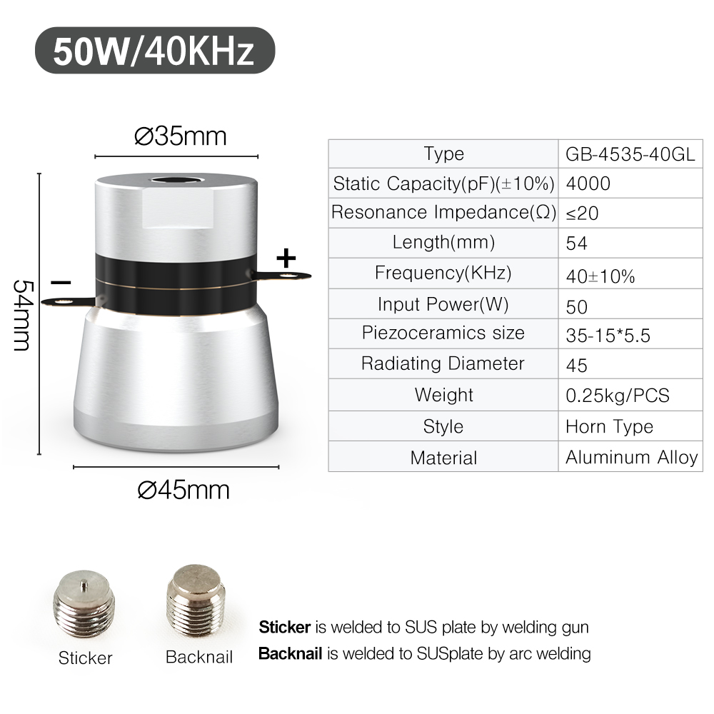
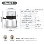
- Model: GB-4535-40GL
- Style: Horn Type
- Resonance Frequency: 40 ± 10% kHz
- Rated Power: 50W
- Static Capacitance: 4000 ± 10% pF
- Resonance Impedance: ≤ 20 Ω
- Piezoelectric Ceramic Dimensions: 35 mm x 15 mm x 5.5 mm
- Top Diameter: Ø35 mm
- Radiating Surface Diameter: Ø45 mm
- Overall Height: 54 mm
- Weight: 0.25 kg
- Material: Aluminum Alloy
Wiring & Assembly
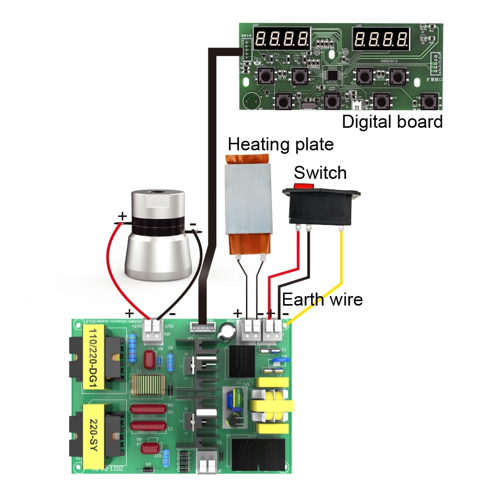
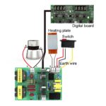
- Connect the Digital Board to the drive board using the multi-pin interface cable.
- Connect the Heating Plate leads to the terminal block marked
Heat. - Connect the AC Power Switch to the main input terminals: Live (
L), Neutral (N), and attach the Earth Wire securely to the cleaning tank chassis. - Connect the Transducer positive terminal (+) to
OUT+and negative terminal (-) toOUT-.
Instructions for Wiring Between Circuit Board and Transducer
- The circuit board cannot be powered on without load.
- After installation, it is better not to start the machine for more than 1 minute without any cleaning fluid.
- The 60W drive board is one transducer and is connected to the terminal of the circuit board. One circuit board and one transducer are used together.
- The 120W drive board is two transducers and is connected to the terminal of the circuit board. One circuit board and two transducers are used together.
- The 180W drive board is three transducers and is connected to the terminal of the circuit board. One circuit board and three transducers are used together.
- OUT + is connected to the positive pole of the transducer, OUT – is connected to the negative pole of the transducer. The power supply L of the drive board is positive and N is negative. Parallel drive plate Lb is positive and Nb is negative. Heating PTC is positive and N is negative. The display board HT is the interface and the display board J1 is the temperature probe interface. Remember not to get it wrong.
(Note: The voltage at the output terminal of the circuit board is about 400V. Pay attention to safety. It is best to have a leakage protection switch on the input power supply to ensure safety!)
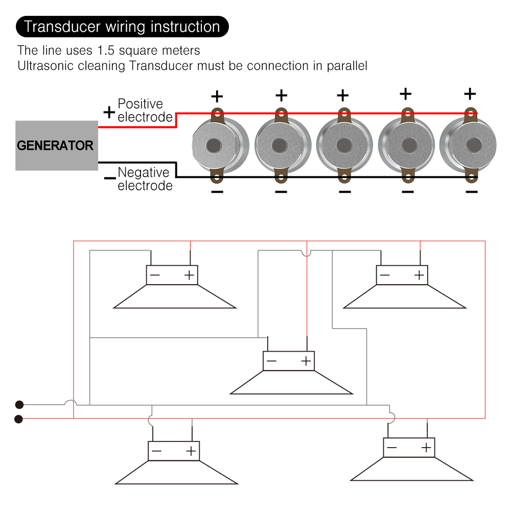
Multi-Transducer Parallel Connection
- Wiring Standard: 1.5 mm² wire.
- Connection Type: Ultrasonic transducers must be connected in parallel.
- Connect all transducer positive terminals (+) to generator
OUT+. - Connect all transducer negative terminals (-) to generator
OUT-.
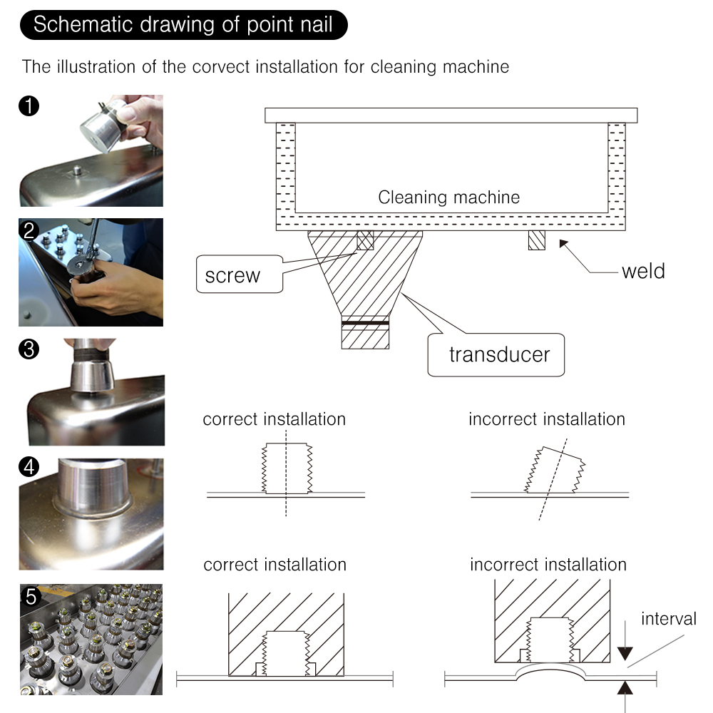
Transducer Stud Installation Instructions
- Stud Attachment Methods:
- Sticker Stud: Welded to the stainless steel (SUS) plate using a capacitive discharge stud welding gun.
- Backnail Stud: Welded to the SUS plate using manual arc welding.
- Installation Requirements:
- Studs must be welded perpendicular (at a 90° angle) to the tank surface.
- The bottom plate of the cleaning tank must remain completely flat without deformation, dents, or gaps.
- Apply bonding agent evenly, thread the transducer tightly onto the stud, and ensure no gap exists between the radiating horn face and the tank bottom.
Customer Reviews
You must be logged in to post a review.
Reviews
Clear filtersThere are no reviews yet.